By Michelle Kurosawa, Founder & CEO, Additiveio —
Ti-6Al-4V is the most widely used titanium alloy in LPBF aerospace applications. It is also one of the more parameter-sensitive materials in the powder-bed-fusion process window. Small changes in laser power, scan speed, or hatch spacing produce measurable changes in part density, porosity morphology, microstructure, residual stress state, and ultimately mechanical properties. For flight hardware, where property repeatability is a qualification requirement, parameter optimization is not a one-time setup task — it is an ongoing commitment to process control.
This article covers the key parameter relationships in Ti-6Al-4V LPBF, the failure modes that emerge at the extremes of the process window, and the approach we use at Additiveio to lock parameters for flight-grade repeatability.
The volumetric energy density framework
The most commonly cited first-order metric for LPBF parameter selection is volumetric energy density (VED), defined as:
VED = P / (v × h × t)
Where P is laser power (W), v is scan speed (mm/s), h is hatch spacing (mm), and t is layer thickness (mm). VED is expressed in J/mm³.
For Ti-6Al-4V, the density-optimized process window in the published literature generally falls between approximately 50 and 80 J/mm³, with published studies clustering around 60–70 J/mm³ for >99.5% relative density. However, VED as a single metric is a significant oversimplification. Two parameter sets with identical VED can produce very different microstructures, porosity morphologies, and residual stress states depending on how the energy is delivered. Specifically, a low-power, low-speed combination (high dwell time per unit area) and a high-power, high-speed combination with the same VED will produce different melt pool geometries, different solidification rates, and different columnar grain structures.
VED is a useful first-order screening tool. It is not a substitute for empirical density measurement and microstructural characterization across the parameter space.
Porosity mechanisms and their parameter signatures
Two distinct porosity mechanisms operate in LPBF Ti-6Al-4V, and they have opposite parameter signatures. Understanding which mechanism is active in a given density deficiency guides the parameter correction.
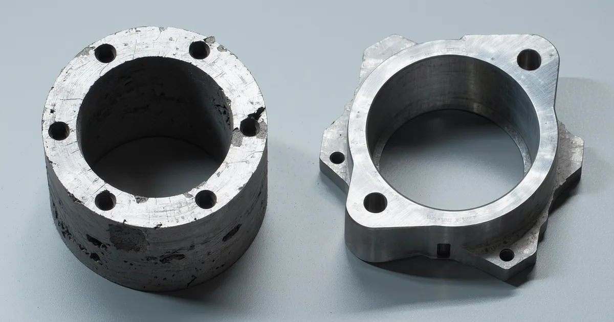
Lack-of-fusion porosity
Lack-of-fusion (LOF) porosity occurs when the melt pool does not fully penetrate the current powder layer and re-melt a sufficient depth into the previously consolidated layer beneath it. The result is an irregular, angular void bounded by partially melted powder particles — a distinctive morphology that is readily identifiable in optical or SEM cross-section. LOF defects are particularly damaging to fatigue life because the angular void tip acts as a stress concentrator.
The parameter signature for LOF is insufficient energy delivery: too low laser power, too high scan speed, too wide hatch spacing, or too thick a layer. In the VED framework, LOF occurs below the density-optimized window — typically below ~50 J/mm³ for Ti-6Al-4V at standard layer thicknesses. The correction is straightforward: increase power, reduce speed, reduce hatch spacing, or reduce layer thickness.
Keyhole porosity
Keyhole porosity arises from a different physics regime. When laser power is high relative to scan speed, the melt pool depth exceeds approximately 3× the beam radius, creating a vapor-depressed keyhole cavity below the melt surface. The keyhole is unstable — it collapses periodically, trapping vapor and producing spherical or near-spherical pores at the melt pool root. In CT cross-section, keyhole pores are recognizable by their spherical morphology and their consistent location at the bottom of individual scan tracks.
Keyhole pores are less damaging to static strength than LOF defects (the spherical geometry is a less severe stress concentrator), but they are still problematic for flight hardware because they increase scatter in fatigue life data and may not be eliminated by HIP if the trapped gas pressure exceeds the applied isostatic pressure.
The parameter signature for keyhole is excessive energy delivery: too high laser power relative to scan speed, or too slow scan speed relative to power. The correction is to reduce power, increase speed, or both — but without crossing back into the LOF regime. The process window between LOF and keyhole narrows at higher layer thicknesses, which is one reason that aerospace AM operations tend to use 30–40 µm layer thickness rather than the 60–80 µm that is common in non-critical industrial applications.
Microstructure and the cooling rate relationship
Ti-6Al-4V in the as-printed LPBF condition has a characteristic martensitic microstructure: fine acicular α' phase, produced by the rapid solidification and cooling rates that are inherent to the LPBF process. Cooling rates in the melt pool are estimated to be on the order of 106–107 K/s — far faster than any conventional casting or wrought process. At these rates, the β phase formed on solidification does not have time to transform to the equilibrium lamellar α+β microstructure; instead, it transforms to martensitic α', which has elevated hardness and tensile strength but reduced ductility relative to the equilibrium microstructure.
The as-printed microstructure also exhibits significant anisotropy. The thermal gradient in the build direction (Z) is large, driving preferential columnar grain growth along Z. This produces anisotropic mechanical properties: Z-direction (build direction) properties are typically 5–15% lower in tensile strength and notably lower in fatigue life compared to XY-plane properties, depending on porosity distribution and surface condition of the Z-direction face.
Post-build heat treatment is not optional for flight hardware for this reason. Stress relief annealing at approximately 650–700°C (below the β transus at ~995°C for Ti-6Al-4V) transforms the martensitic α' to a fine lamellar α+β microstructure, reduces residual stress, and substantially improves ductility and toughness. This is followed by HIP at 900°C / 100 MPa argon for typical aerospace cycles, which closes any remaining closed-porosity and further homogenizes the microstructure.
The combination of stress relief + HIP produces mechanical properties that meet or exceed the AMS 4928 wrought Ti-6Al-4V requirements: UTS ≥ 930 MPa, 0.2% YS ≥ 860 MPa, elongation ≥ 10%, reduction in area ≥ 20%. The as-built microstructure is a starting point; the final properties are a function of the complete thermal processing sequence.
Scan strategy effects on residual stress and distortion
Residual stress is one of the most significant process challenges in LPBF Ti-6Al-4V. The rapid heating and cooling cycles produce steep thermal gradients that drive tensile residual stresses near the top surface and compressive residual stresses in the bulk. In thin-walled features or unsupported overhangs, these stresses can cause warping during the build or delamination at the layer interface — both of which are build-stopping failure modes.
Scan strategy — the pattern and sequence by which the laser traverses each layer — has a significant effect on residual stress distribution. The most commonly compared strategies are:
- Stripes: Parallel scan vectors of fixed length, filling the cross-section in one or two passes. Simple to implement; produces anisotropic stress distribution aligned with the scan direction.
- Chessboard (island) strategy: The cross-section is divided into square islands, each scanned independently with the scan direction rotated 90° between adjacent islands. Reduces the maximum length of any continuous scan vector, which limits the temperature gradient extent. Produces more isotropic stress distribution than stripes.
- Rotating stripe: Stripe strategy with rotation of the scan vector direction by a fixed angle (typically 67°) between layers. Reduces anisotropy over the build height.
For flight-hardware brackets with complex geometry and thin-wall features, we use a rotating stripe or chessboard strategy depending on feature geometry. Thin walls benefit from shorter island scan vectors; large cross-sections with no unsupported features tolerate rotating stripe without distortion issues. The strategy is specified in the build plan as a controlled parameter, not left to machine default settings.
Support structure design and its effect on part quality
Support structures in LPBF serve two functions: they anchor the part to the build plate (or to other features above the build plate) to resist warping forces during the build, and they provide conductive pathways for heat dissipation from overhanging surfaces that would otherwise overheat and produce soot or droplet defects.
For Ti-6Al-4V, surfaces with an overhang angle below approximately 40–45° from horizontal typically require support. The design of those supports has a direct effect on: part surface finish on supported surfaces (the contact points leave witness marks), ease of support removal (supports that are too dense or too stiff require more aggressive machining), and thermal behavior of the supported feature during the build (support density affects local cooling rate).
DfAM review — the 48-hour engineering review we perform before writing a build plan — focuses heavily on support accessibility and geometry. Supports that cannot be accessed by a standard tool after wire EDM separation from the build plate are a build-design failure that will delay or prevent part release. We flag these issues in the DfAM review, before any powder is loaded, because a support design problem discovered after the build is a sunk cost in material and machine time.
Parameter qualification and the "parameter lock" concept
Aerospace AM qualification documentation typically includes a process parameter qualification record (PPQR) or equivalent: a document that records the specific parameter set used for a given material-machine combination, the density and mechanical property data generated to validate that parameter set, and the authorized ranges around the nominal values within which production may operate without re-qualification.
At Additiveio, we maintain a parameter library for Ti-6Al-4V ELI at each layer thickness we support (currently 30 µm and 40 µm). The nominal parameters in this library are validated by coupon builds (test specimens built alongside or independent of customer parts) with destructive density measurement (Archimedes method and optical metallography), hardness testing, and where required, tensile coupon testing. The coupon data is archived and available for customer review as part of the process qualification records.
When a customer part enters production, the build plan references the approved parameter library entry. Any change to the machine hardware, powder specification, or layer thickness that would affect the validated parameter set triggers a re-qualification event before production continues. This is the "parameter lock" that appears in our qualification flow: it is not simply a machine setting — it is a controlled document that links the specific process to the specific material qualification data.
In-process monitoring as a quality gate
Layer-resolved in-process monitoring is increasingly used in aerospace AM operations as a supplement to — not a substitute for — destructive coupon testing and NDT. The primary monitoring modalities in LPBF are melt pool imaging (photodiode or high-speed camera observing emission intensity from the melt pool) and layer topography scanning (structured light or laser profilometry of the consolidated layer before the next powder coat).
Both techniques produce large volumes of data per build. The practical value is in deviation detection: a melt pool emission anomaly that correlates with a process parameter excursion, or a layer topography deviation that correlates with a recoater interference event. These events are flagged for engineering review and, if the deviation exceeds the established control limit, trigger a build hold.
The monitoring data is archived as part of the build record. It does not replace the NDT inspection after the build — micro-CT is still the definitive technique for internal defect characterization. But it provides a build-time quality record that is documented independently of the finished-part inspection, which strengthens the overall traceability chain.
The repeatability standard for flight hardware
The end goal of parameter optimization is not the best possible single result — it is the most repeatable result within acceptable limits. A parameter set that produces 99.7% density on one build and 99.2% density on the next is not a controlled parameter set, even if both values exceed the AS9100-ready threshold. Repeatability is demonstrated by running multiple builds under the same parameter set and process conditions, and showing that the output scatter is within the acceptance limits of the qualification specification.
This is why we run coupon specimens with production builds, why we maintain build-log data for every layer of every build, and why parameter changes — even seemingly minor ones — require an engineering review before implementation. The qualification is not just of the nominal parameter set. It is of the entire process system: machine, material, environment, and procedure, operating within defined limits.